AM Radio Transmitter
April 2019
with Luis Collado
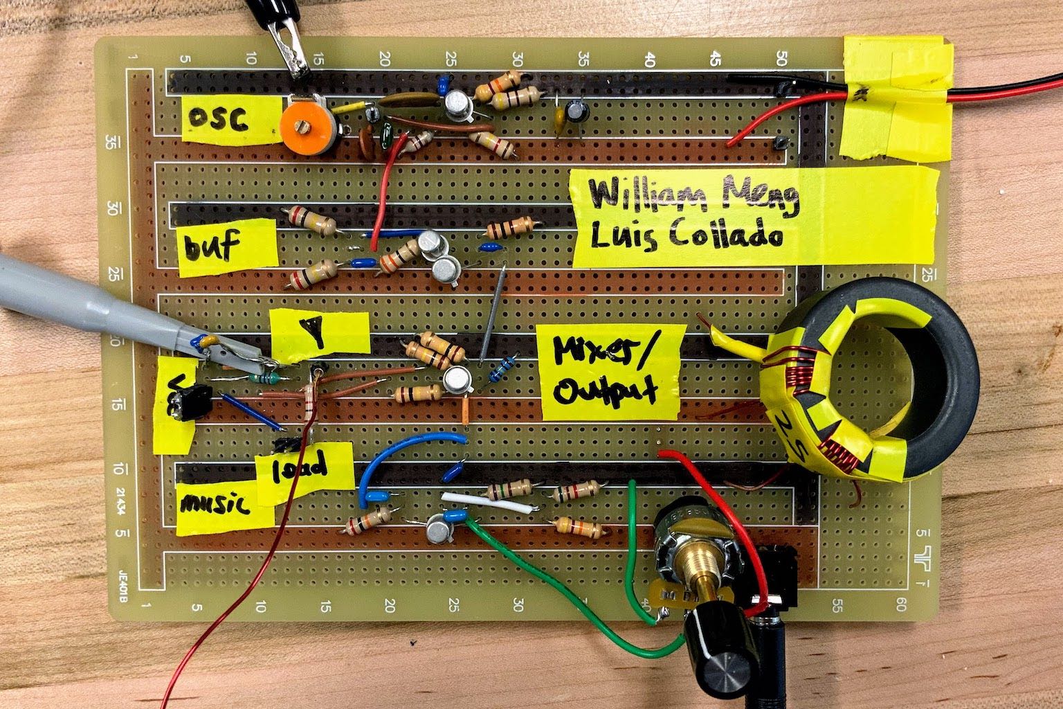
For my Communication Circuits class taught by Prof. Yannis Tsividis, we designed and built an AM Radio transmitter using only 5 transistors plus passive components. The transmitter consists of 5 functional blocks:
- Colpitts Oscillator – generates the carrier frequency
- Buffer – buffers the output of the Colpitts Oscillator
- Audio Amplifier – preamp for the input audio signal
- *Mixer – uses the audio signal to modulate the amplitude of the carrier
- *RF Power Amplifier (PA) – amplifies the AM signal to sufficient power for transmitting
*The mixer and PA are implemented with the same transistor in the output stage.
The amplitude modulation is achieved by utilizing the non-linearity of a bipolar transistor’s output current with respect to input current in order to performing mixing (ie. multiplication) of two signals which are combined additively at the transistor’s input. The two signals which are fed into the modulator are the radio frequency carrier (from the Colpitts Oscillator) and the audio signal (from the preamp). The carrier is subtracted from the audio signal (which is equivalent to adding the carrier with a 180º phase shift) by applying the audio signal to the transistor’s base and the carrier to the transistor’s emitter. Once the modulated signal, along with unwanted harmonics, has been produced in the form of the transistor’s collector current, a parallel RLC network acts as a bandpass filter so that the carrier and sidebands are passed to the antenna, while other frequency components are (mostly) rejected.
More details can be found in our report.
Here is a video of it in action:
And our demonstration for Prof. Tsividis:
comments powered by Disqus